
How an item on a shelf becomes a record in AMSY.
A radio wave powers a battery-free tag, the tag answers with an identifier, and software turns that identifier into a counted, reconciled asset. This page follows that path from the chip to the report.
- 860–960 MHz band
- ISO/IEC 18000-63 Type C
- GS1 Gen2 · RAIN RFID
- 0 batteries in the tag
- Reader talks first
Architecture, frequencies and standards
Radio-Frequency Identification identifies objects through radio waves. A working system has four layers: a tag on the asset, a reader and antenna, middleware, and a backend information system.
Tag
Stores identification data on the asset.
Reader + antenna
Retrieves that data over the radio interface.
Middleware
Collects, filters and forwards the resulting observations.
Backend
Links identifiers to asset records and reads observations in the context of business processes.
Inside a tag
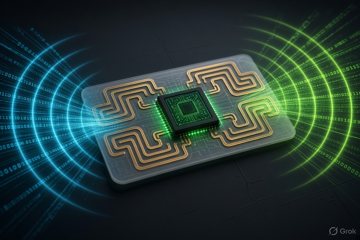
The chip manages power, executes protocol commands and controls access to memory. The antenna receives energy and commands, and lets the tag answer.
Antenna design and placement must suit the object the tag is attached to. Metal, liquids and tag orientation can change radio performance a great deal, which is why one tag type does not fit every product.
Memory: four logical banks
Gen2 defines four memory banks. What is actually available depends on the chip.
- MB00
Reserved
Access and Kill passwords, subject to chip capabilities.
Kill password · 32 bitAccess password · 32 bit - MB01
EPC
The identifier of the object and its protocol-control information.
CRC-16PC bitsEPC · length depends on scheme and chip - MB10
TID
Chip manufacturer and model. A chip serial number is included where the chip supports it.
Class IDMaker + modelSerial (if supported) - MB11
User
Application-specific data. Capacity depends on the chip.
Optional · chip dependent
Bank layout shown schematically, not to scale.
Operating frequencies and compliance
RFID has no single universal frequency. For UHF, ISO/IEC 18000-63 defines the Type C air interface across 860–960 MHz, and the published scope of GS1 Gen2 Release 3.0.1 is 860–930 MHz. Neither range permits operation across the whole spectrum in every country.
Radio communication, reading and data transfer
Energy harvesting and backscatter
The reader sends a radio-frequency signal through its antenna. A passive tag converts part of the energy it receives into electrical power and wakes its circuit.
After a valid command, the chip changes the electrical load on its antenna. That changes how much of the signal the antenna reflects, and so writes data onto the reflected wave. This is backscatter modulation. The reader receives the reflection and demodulates it to recover the data.
The exchange follows an Interrogator-Talks-First model: the reader starts every conversation and tags answer only when commanded.
Identifying many tags at once
With several tags in range, the reader runs an anti-collision procedure to separate their answers. A basic Gen2 inventory round has five steps.
- QueryReader sends parameters such as Session and Q.
- Slot pickEach tag draws a random slot from a window of 2Q slots.
- RN16When its slot comes up, a tag sends a temporary 16-bit random number.
- ACKReader returns that number to acknowledge one tag.
- EPC replyTag sends its EPC with control and error-checking fields.
SIMULATION Each tag picks a slot at random. A slot with one tag yields a clean read; two or more collide. The reader adjusts Q between rounds to balance collisions against empty slots.
What reaches the software
| Field | Comes from |
|---|---|
| EPC | tag memory |
| TID | tag memory only if a read operation was performed |
| Antenna ID | reader side |
| First / last seen | reader side |
| Read count | reader side |
| RSSI | reader side signal strength |
Which fields you get depends on the reader and its report configuration. The identifier comes from the tag; timestamps, antenna IDs and RSSI are observation metadata created by the reader.
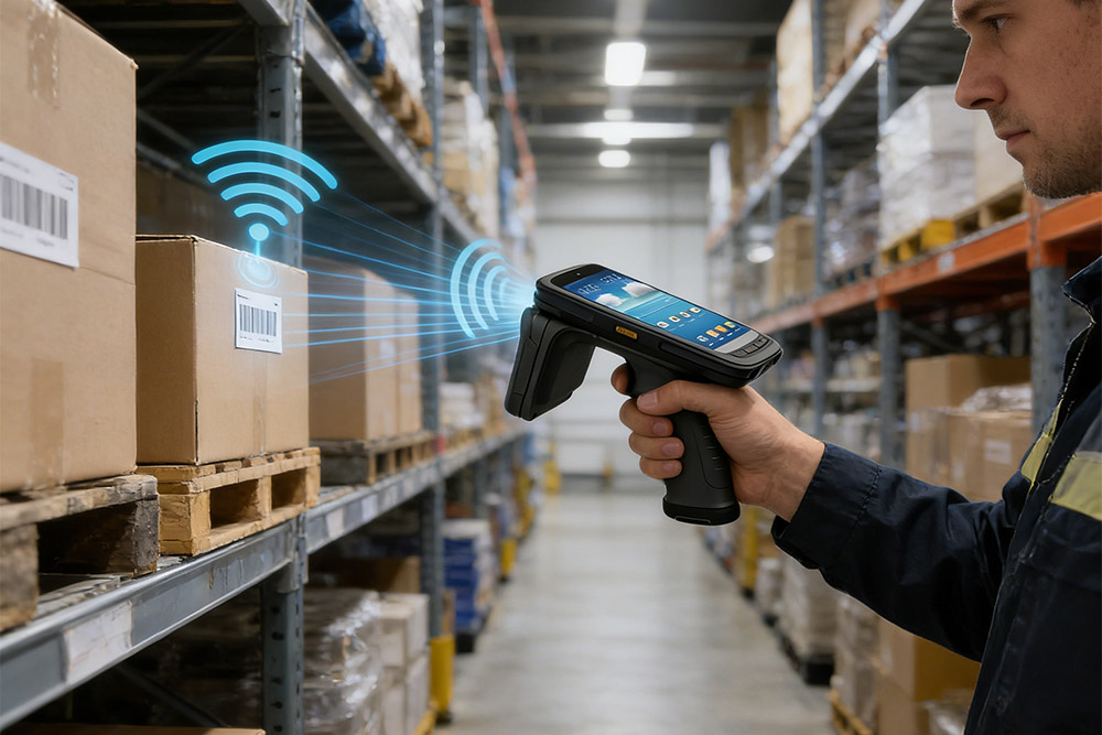
Readers speak to software through the standard Low Level Reader Protocol (LLRP) or a vendor interface. LLRP controls radio operations and delivers tag reports. A reader may sit on a network directly, or connect to a phone or computer over USB or Bluetooth, and host software then forwards observations to the backend.
Read range is not a fixed number
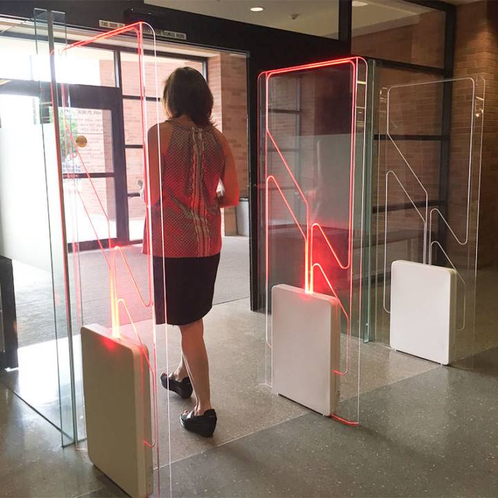
Reader power, chip sensitivity, antenna characteristics, tag orientation and the installation environment all change it. More power can also mean unwanted reads from neighbouring items. Good design starts from the interrogation zone the task needs.
Backend identification, events and reporting
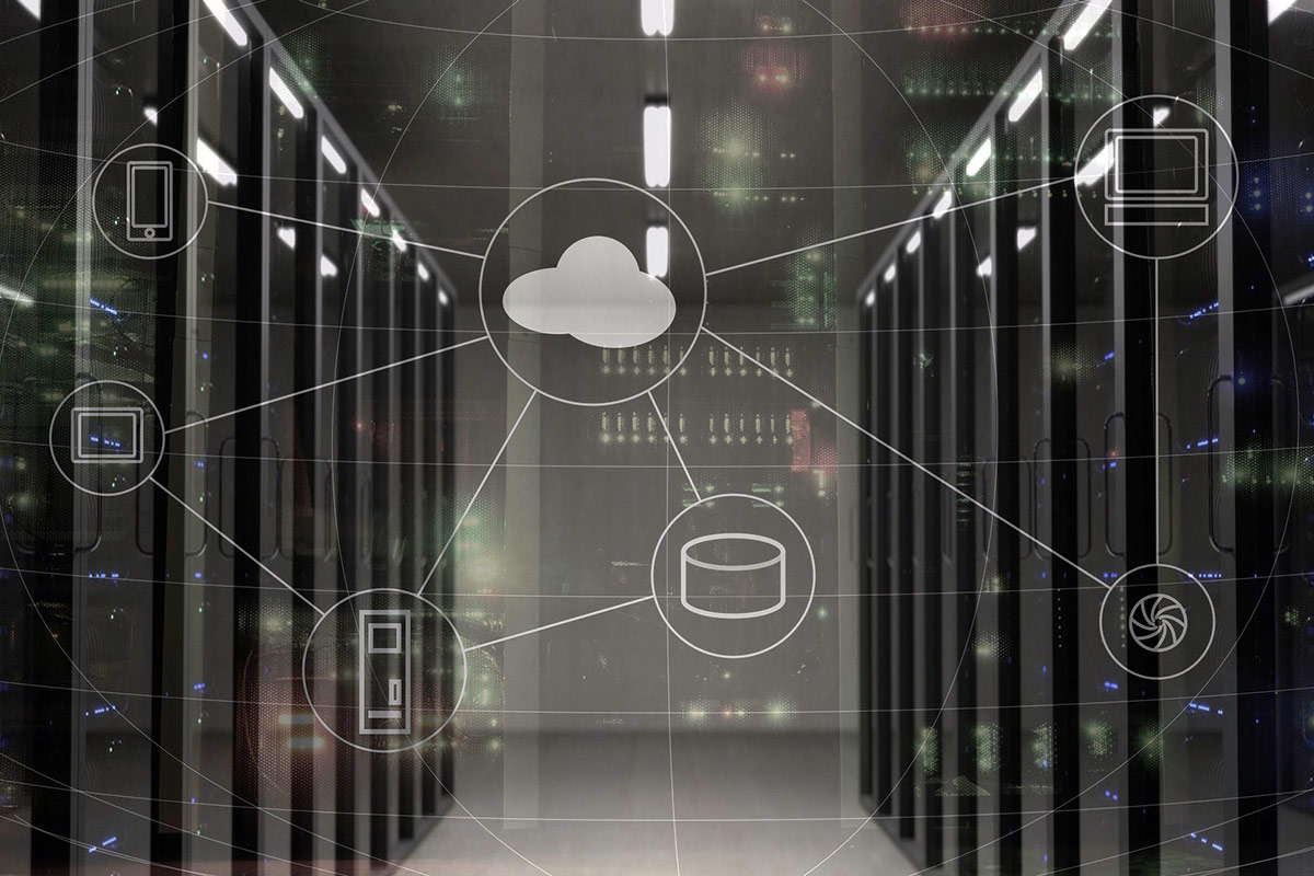
The server receives digital observation records, not radio signals. To make sense of them, the application needs a valid link between a tag identifier and an asset.
Commissioning a tag
In the proposed implementation, commissioning stores the internal asset ID, EPC, organisation and binding status. TID can be recorded as well. After an EPC is programmed, the application reads it back and compares it with the intended value before it confirms the tag.
- STEP 1
Choose
Pick the asset and the EPC to assign.
- STEP 2
Program
Write the EPC to the tag.
- STEP 3
Read back
Read the EPC again from the tag.
- STEP 4
Compare
Check it equals the intended value.
- STEP 5
Bind
Save asset ID, EPC, organisation, status (TID if needed).
Resolving an observation
When a read arrives, the server checks the identity and permissions of the device or user, checks the identifier format, then searches only inside the authorised organisation's records. Names, images, prices and history come from the database. They do not need to live on the tag.
From reads to business events
A tag sitting still can be read many times in a few seconds. Those reads must not count as separate assets, so software aggregates them by identifier, scan session, time window and interrogation zone. Raw observations can be kept for audit and diagnosis.
One observation does not prove an item was sold, delivered or removed. That conclusion needs context: which device saw the identifier, where, when, and which process was running.
EPCIS
A standard framework for recording and exchanging events: what was involved, when, where and why. Not required for every internal application, but it supports interoperable exchange between systems.


Reconciliation and exception reporting
For an inventory session, E is the expected set of identifiers and O the set of unique observed identifiers. Try it: tick the items the reader found.
Reliability and security
Idempotent events
Unique event IDs mean a retransmitted message never applies the same operation twice.
Two clocks
Observation time and receipt time are stored separately, with local buffering for network drops.
Audit trail
Who observed what, from which device, and what the system did with it.
Encrypted and scoped
Traffic is encrypted. Each device is limited to its own organisation and permitted operations.
Standards referenced
- ISO/IEC 18000-63
Type C UHF air interface, 860–960 MHz. - GS1 EPC UHF Gen2 v3.0.1
Air-interface protocol, scope 860–930 MHz. - GS1 EPC Tag Data Standard
Encoding rules for GS1-based identification. - LLRP
Low Level Reader Protocol for reader control and tag reports. - GS1 EPCIS
Event capture and exchange framework. - ISO/IEC 29167
Air-interface cryptographic suites.